TheCodersCorner.com items tagged with switches.

Arduino digital input and output tutorial
In this tutorial and accompanying youtube video (left), I discuss how Arduino inputs and outputs work. Arduino 8 bit boards are mainly based on Atmel AVR chips, in fact the Mega is named after the chip number AVR-Mega-2560. Outputs on the AVR chips are much more versatile than they first look, and the video covers this in detail. If you are...

Working with and de-bouncing switches for Arduino
When we press a button that's connected to an Arduino input, it is likely that the button will momentarily "flicker" between the on and off state. This gives false readings for a short period of time after the button is pressed. Problems caused by this can range from the mild annoyance of a slight flicker, to doing something more than once...
These may be of interest
- Similar - Write XML with GroovyBuilder
- Similar - Wrapping JFreeChart as a Groovy builder
- Similar - Reading XML in groovy using XmlParser
- Similar - Generate an ATOM feed with GroovyBuilder
- Similar - Groovychart Bar chart with fixed colour

Supporting us
We maintain several popular embedded projects and work hard to make them even better. If you're looking for commercial services, please do consider us.
Alternatively, you can buy us a coffee to say thanks.
Sharing links
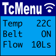
Learn about TcMenu
Learn about our rapid development framework TcMenu.